February 2022 -
Part of the experiment with receiving antennas on low
bands, myself and Ahmed 3V1B built a couple of PA0RDT Mini Whip
antennas for a later possible use as a receiving array..
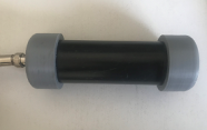
The active antenna was powered via biasT. A pipe
enclosure contained the circuit for outdoors
installation.
More information on the MiniWhip design can be found
here.
The tests that were carried out used the MiniWhip
powered by 9V Battery through the BiasT. The feed voltage
passes through 20m of RG-174 coax and reaches the
antenna at about 7.5V.
A ground
connection has been connected to the coax shield at receiver end.
Mounting of
the antenna was at about 4m high.
I also used an MLA30+ powered via USB and beaming north
(where most of the signals are coming from!). Almost the
same height as for the MiniWhip.
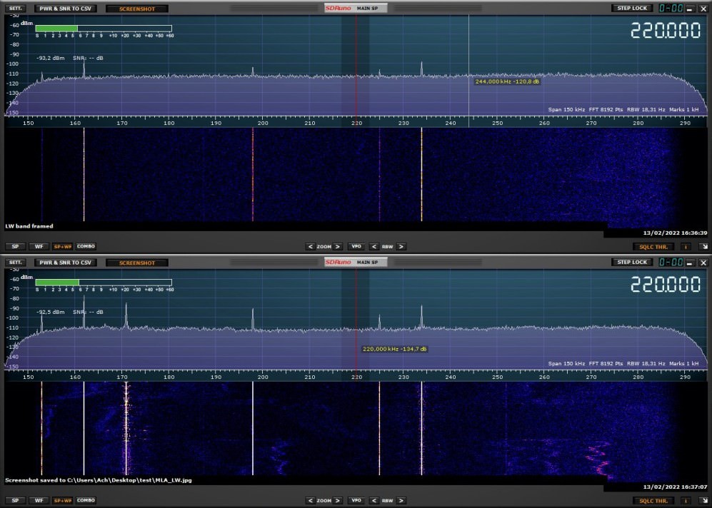
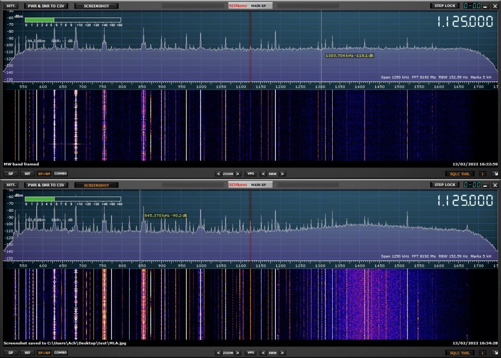
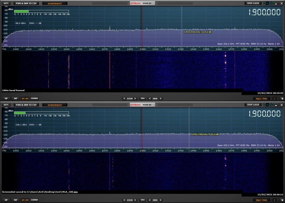
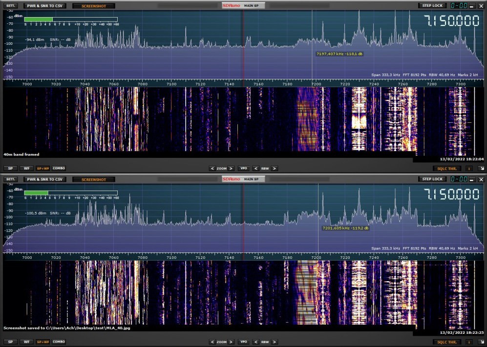
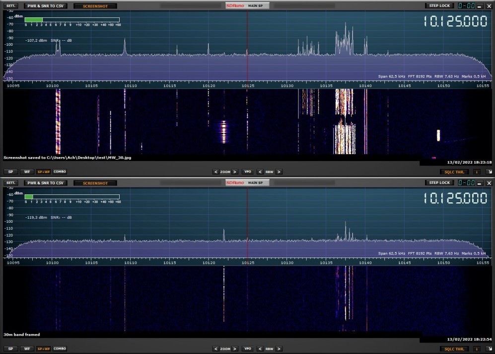
The comparison waterfall screenshots can be found below with the
MLA waterfall being the upper and the MiniWhip's one
being the lower.
The MiniWhip showed excellent performance on the
lower bands (MW and below) compared to the MLA30+.
The MLA30+ started to be better on 160m and above except for 40m
(for some reason!).
Ground connection on the MiniWhip did reduced noise floor on the LW and
below by few db's. The antenna has to be installed
away from noise sources.
Adjusting MiniWhip height showed linear
impact on the signal strength.
3V8SS Reverse Beacon Node - Upgrade to RedPitaya
Back in July 2020, the YASME Foundation has allocated
funds for a project to expand the Reverse Beacon Network
nodes.
These new nodes are being added in regions where there
is a need for reception reports to support amateur radio
operation and where those reports will also have
scientific value for geophysical research.
I did receive Tunisia's RedPitaya card that could be
easily turned into an SDR. Redpitaya allows for 8 bands
decoding simultaneouly - per receiver! It can operate
two receivers in the same time!
A copy of Skimmer Server is needed to perform CW
decoding on various bands at a time. There is a
possibility to run two of them, one for each receiver.
The RedPitaya uploads huge amounts of digital data to
the Skimmer PC (130 Mbps upload speed for typical for 15
-band 192 kHz skimming). A Gigabyte switch is needed.
One antenna port can be used for both receivers. I'm
segregating them to be able to line up two antennas (for
Low and High bands).
KF5EYY SO2R & 6x2 Controller
This design of the SO2R is an improvement to KF5EYY SO2R
v2
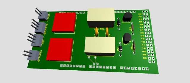
(See below). The audio switching part now includes 1:1
transformers mounted on the PCB. Two new PCBs were added
to control a 6x2 Antenna Switching system via OTRSP (Wintest,
DXLog or any logging software that supports this
protocol).
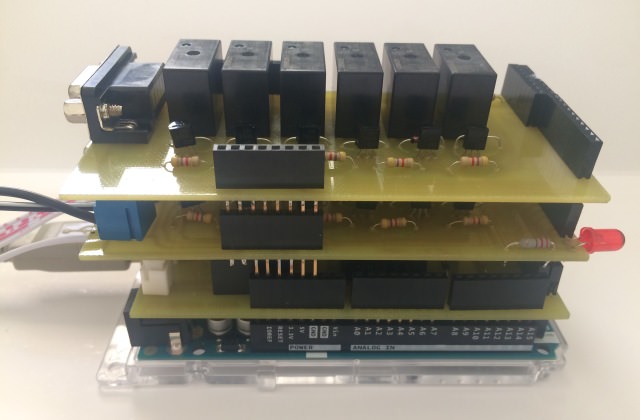
PCBs 3D design on
Proteus
The PCBs are designed to be stacked on an Arduino Mega
controller.
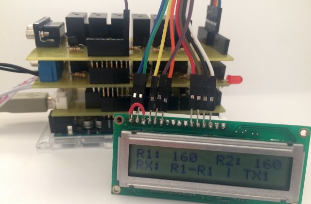
A 6x2 LCD is
used to show the band of each transceiver and the status
of the headset (Left and Right ears).
PCBs mounted on the Arduino Board
The design is based on Relays control. The schematics
are provided
here. Please note that only relays for the control
of Radio 1 Antennas are shown. Similar relays set up
should be considered for Radio 2. Different relays
(G5V-2 and G5Q-1A) were used in
PCBs 1 and 2 due to unavailability of components in
local market. Simple contact relays (G5Q-1A) can be used
for both.
OTRSP is used to control audio in the headset and to
'read' each radio band to switch the 6x2 to the
appropriate antenna. OTRSP Properties (in Wintest) have
to be configured for each band (AUX11, AUX12, etc.). It
is recommended to use a port monitoring software (ie.
Device Monitoring Studio) to make sure the device
received the right command from the logging software.
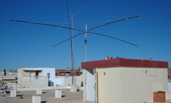
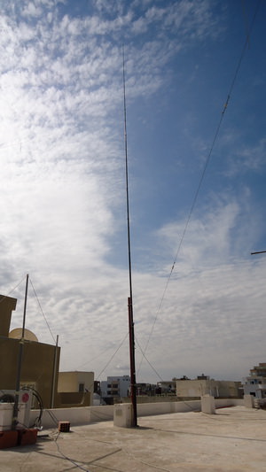
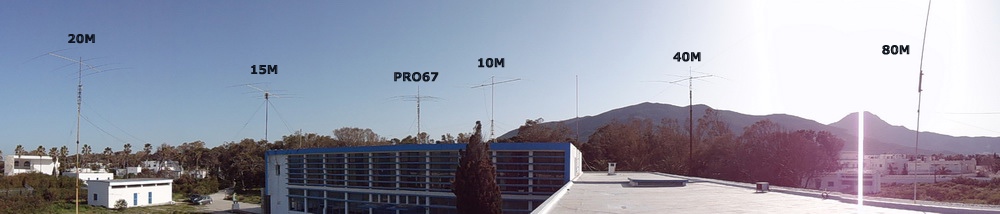
Phased Verticals for 40m Band
In 3V8SS Station, all antennas have to be squeezed on
the roof area. The station is equipped with a 7 Element
CT-37HF Yagi for high bands installed at 7m high from
the roof. Not far from it (around 8m away) a 5 bands
Spider beam is installed at lower height. For low bands,
the station is equipped with an inverted-V for 80 and a
Ground Plane wire vertical for 40m.
With the sun entering low sunspot cycle, I was thinking
how to improve my QSO count on low bands and more
specifically on 40m. Being close to Europe is a big
advantage.
Back in 2009, the 3V3S team from Germany have installed
an 18m vertical for 80/160 using Spiderbeam poles. This
fiberglass vertical was broken two times.
Fortunately, a 12m length of it is kept unharmed. I
decided then to use it as a second element to the
original 40m band - 12m length vertical antenna. I
started reading in antenna books and websites about the
best configuration. I then decided to make phased
verticals using Christman method.
I shared the ideas with Ahmed 3V8CB and Ali 3V/F4HJD,
both active members of ARAT. They were more than happy
to come and give it a try.
Our objective was to have some gain towards Europe (at 0
deg Az) and NA/AS (respectively at 350 and 20 deg Az).
Africa is behind us so there was no need to consider a
direction switching relay.
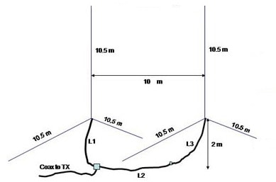
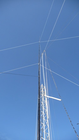
Phased Verticals Schematics
We decided to move a little bit the original vertical
and get some distance from the Yagi tower and Spiderbeam.
Then we started making use of the old 80/160 poles as a
second vertical. Both wire verticals were having two
radials. Once up, we started cutting wire length till an
SWR of 1.5:1 is obtained. Both verticals are
electrically similar. We were a bit concerned about the
electrical impact of the 5m mast holding up the new
vertical.
I used VA7ST Christman Phasing calculator to calculate
feedline lengths for an operating frequency of 7.050
MHz. A velocity factor of 0.66 was used for RG58 (50
Ohms). Both antennas were fed by 84-degree feedlines
(about 6.5m) with additional 72-degree (about 5.5m) to
the northern vertical (the front element). We didn’t
have an antenna analyser to further adjust lengths, all
had to be fixed by experimentation.
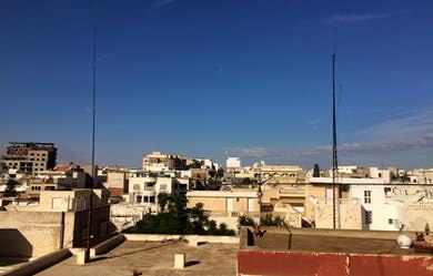
Phased Verticals installed
at 3V8SS
The triple point (where both feedlines are connected to
the main coax) was mechanically attached. Myself, Ali
and Ahmed made RX and TX experiments by lining up one
element then two elements and check the performance. We
checked as well the F/B Ratio by manually switching the
feedlines between the two verticals.
The SWR of the system was very acceptable (1.5:1 on
almost the entire 40 band). Here below are audio
recordings of how RX and TX were improved by the new
system:
TX Audio recording: my signal as recorded by
ARDAM WebSDR located in Andorra which uses a half wave
dipole for 40m: 2016-05-08 10:14Z 7030.0kHz
The first 55 seconds is using the phased vertical. At
2:40, I used a single vertical (old configuration). The
difference is clear!
RX Audio Recording: IK5OJB on 40m:
0 to 34s: use of phased verticals beaming EU
35s to 58s: use of single vertical
59s to end: use if phased vertical beaming south
KF5EYY SO2R Controller
Given the
unavailability of ham radio equipment in Tunisia, I have decided to build my own
SO2R Controller that should help me in the upcoming 2016 contest season.
I made a deep
search on the net and found several designs; some are transistor based with
front panel control switches and some are micro-controller based.
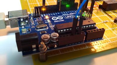
Arduino Uno mounted on KF5EYY SO2R board
I was very
interested in K1XM Arduino
based design. I bought an Arduino Uno device and started familiarizing with it.
I was impressed with the ideas we can realize with it.
K1XM design (and
code) appeared complex to me and uses features that I don't need, I inspired
from it to make my own design and programming of the micro-controller ship. I
have used "Serial Port Monitor" software to better understand how Wintest uses
OTRSP (Open
Two Radio Switching Protocol) to communicate with the device and update the
program accordingly.
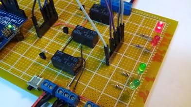
KF5EYY SO2R Controller
Few testing of
Relays command on a breadboard were conclusive, so I purchased components and
built the design on a perforated board.
The device is USB
powered and enables
audio control in the headphones (Radio 1 only, Radio 2 only, Radio 1 Left/Radio
2 Right, Radio 1 + Radio 2 on both ears with possibility to adjust audio level
of Radio 2 for band opening monitoring).
The device enables
also switching TX between the two radios. Dual CQ and other customized operating
scenarios are possible through Wintest.
Relays and Status LEDs
Video of device
testing in 3V8SS club station can be seen
here.
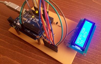
I have then decided to replace the LEDs by an LCD and get the components
implemented on a Printed Circuit Board.
I started testing the LCD on a breadboard. Be careful to the contrast adjust
(pin 3) which should have a resistor connected to the ground. Direct connection
is the silly mistake I made costing me 4 hours of investigating why the LCD does
not show any message!
Further improvements have been brought to the schematics (thanks I4UFH). These
include adding optocouplers to the CW connections to the radios. I also added
capacitors for RF grounding on the audio outlet.
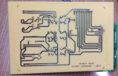
I made the PCB design using Proteus ARES 8. A lot of manual work was done to put
the LCD on one side and the connection wires on the other side.
The Arduino code was improved to inform user Wintest is properly connected to
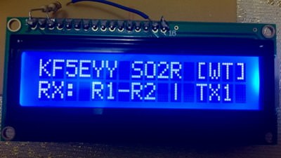
the device. This is shown by a flashing [WT].
KF5EYY SO2R Display
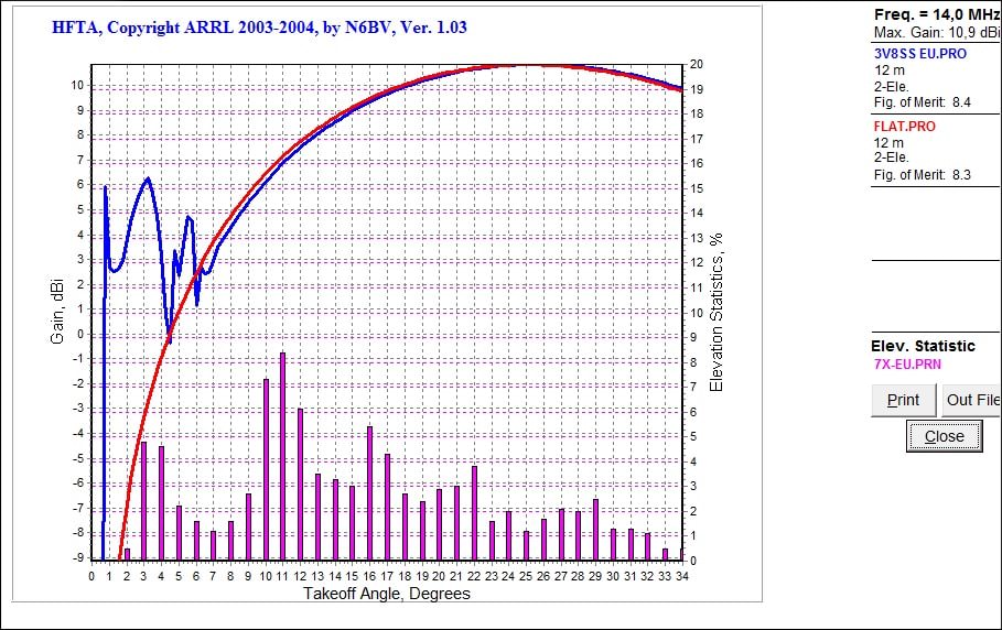
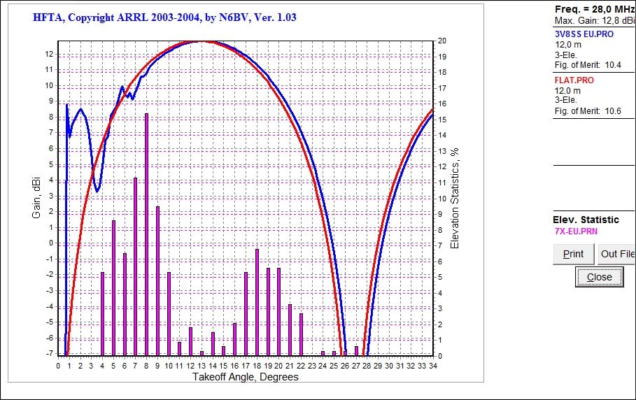
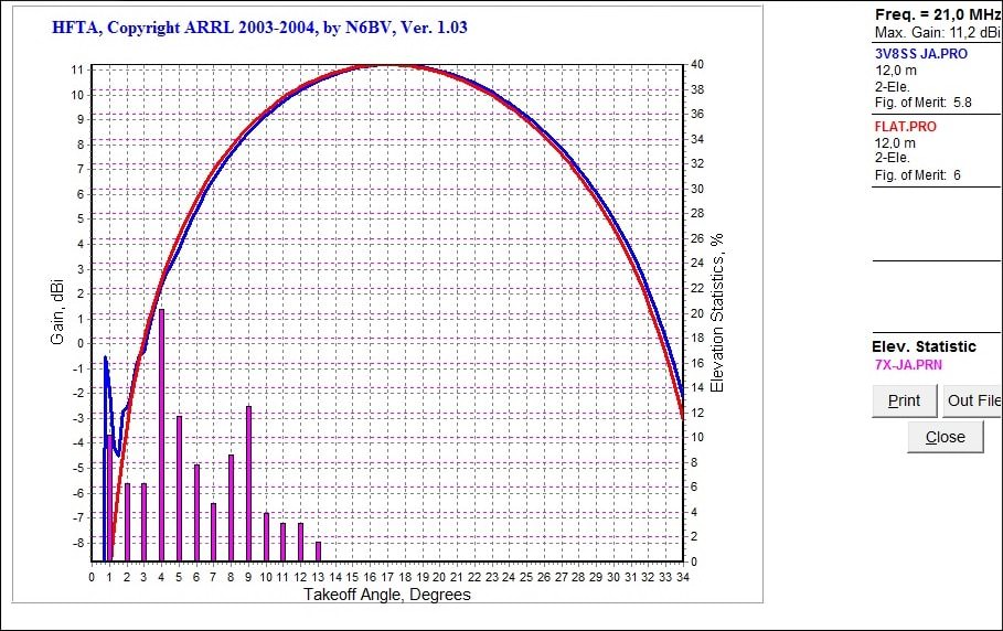
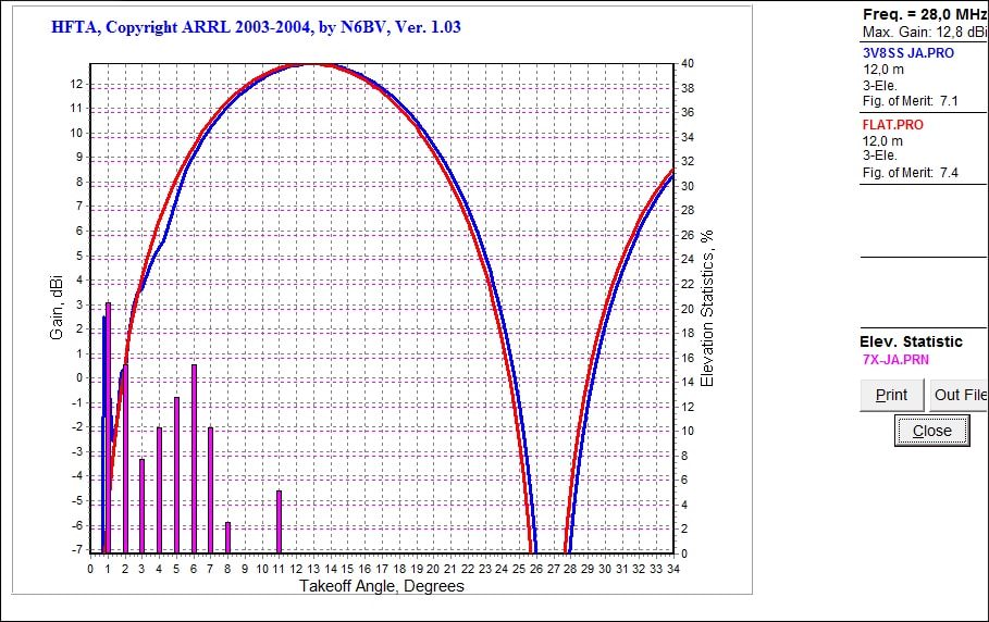
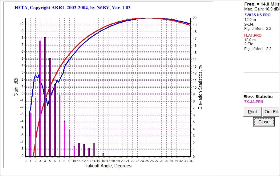
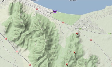
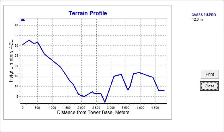
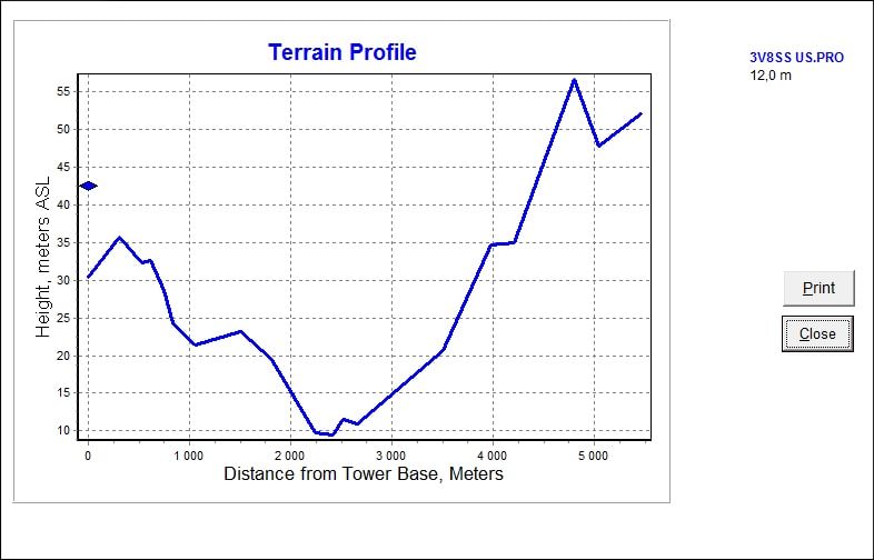
3V8SS Terrain Analysis
I made these terrain analysis to better understand the
impact of location and terrain on 3V8SS station
performance.
The terrain profile files were manually and roughly
populated. The only available angle elevation statistics
are for 7X. These were used since there should be no big
difference.
The results shown perfectly match my seven years
experience operating this station. The problem still
with JA and NA paths on 14MHz; a good percentage of
take-off angles are not workable.
Map it! is a tool that enables users to plot ADIF files
(generated by Logger32) on a rectangular map with great circle lines display. It
also provides information on the plotted stations such us
distance, bearing and the bands in which the DXCC/location
is worked. In this version 1.0, ADIF files shall have
either Lon/Lat coordinates or GridSquare (Maiden).
The tool also enables the plotting of FT8 Log file
(generated by WSJT-X). The purposes can be to compare
performance of RX antennas since the tool displays the
RXed Grids with S/N Ratio color coding (highest S/N for
each grid).
Map it! is a joint effort between myself and Mohamed
7X3TL in an endeavor to make a good use of our spare lockdown time.
Depending on feedback from people, we are planning to
embed more features.
At first glance it is clear that 3V8BB QTH is excellent and these mountains only
affect SA path. However, I wanted to do the exercise, come up with charts that
support this, and why not, look for improvements.
Thanks to N6BV and VA7ST for their support during the elaboration of this work
and to S56A, W1UE and K6TU for their comments and ideas
Call: 3V8SS Location: Sousse City, Tunisia Address: Maison de Scout Avenue Abou Jihed 4011 Hammam Sousse Locator: JM55hu LONG: 10.5941 E
LAT: 35.85662 N
Google map TRX:


 A ground
connection has been connected to the coax shield at receiver end.
A ground
connection has been connected to the coax shield at receiver end. 


